- 您现在的位置:买卖IC网 > Sheet目录1253 > XR18W750/753-0B-EB (Exar Corporation)EVAL BOARD FOR XR18W750/753
�� �
�
�XR18W750�
�WIRELESS� UART� CONTROLLER�
�REV.� 1.0.0�
�IER[5]:� Reserved�
�For� normal� operation,� this� bit� should� be� ’0’.�
�IER[6]:� RTS#� Output� Interrupt� Enable� (requires� EFR� bit-4=1)�
�?� Logic� 0� =� Disable� the� RTS#� interrupt� (default).�
�?� Logic� 1� =� Enable� the� RTS#� interrupt.� The� UART� issues� an� interrupt� when� the� RTS#� pin� makes� a� transition�
�from� low� to� high.�
�IER[7]:� CTS#� Input� Interrupt� Enable� (requires� EFR� bit-4=1)�
�?� Logic� 0� =� Disable� the� CTS#� interrupt� (default).�
�?� Logic� 1� =� Enable� the� CTS#� interrupt.� The� UART� issues� an� interrupt� when� CTS#� pin� makes� a� transition� from�
�low� to� high.�
�5.4�
�Interrupt� Status� Register� (ISR)� -� Read-Only�
�The� UART� provides� multiple� levels� of� prioritized� interrupts� to� minimize� external� software� interaction.� The�
�Interrupt� Status� Register� (ISR)� provides� the� user� with� six� interrupt� status� bits.� Performing� a� read� cycle� on� the�
�ISR� will� give� the� user� the� current� highest� pending� interrupt� level� to� be� serviced,� others� are� queued� up� to� be�
�serviced� next.� No� other� interrupts� are� acknowledged� until� the� pending� interrupt� is� serviced.� The� Interrupt�
�Source� Table,� Table� 9� ,� shows� the� data� values� (bit� 0-5)� for� the� interrupt� priority� levels� and� the� interrupt� sources�
�associated� with� each� of� these� interrupt� levels.�
�5.4.1�
�Interrupt� Generation:�
�?� LSR� is� by� any� of� the� LSR� bits� 1,� 2,� 3� and� 4.�
�?� RXRDY� is� by� RX� trigger� level.�
�?� RXRDY� Time-out� is� by� a� 4-char� plus� 12� bits� delay� timer.�
�?� TXRDY� is� by� TX� trigger� level� or� TX� FIFO� empty.�
�?� MSR� is� by� any� of� the� MSR� bits� 0,� 1,� 2� and� 3.�
�?� CTS#� is� when� its� transmitter� toggles� the� input� pin� (from� LOW� to� HIGH)� during� auto� CTS� flow� control.�
�?� RTS#� is� when� its� receiver� toggles� the� output� pin� (from� LOW� to� HIGH)� during� auto� RTS� flow� control.�
�5.4.2�
�Interrupt� Clearing:�
�?� LSR� interrupt� is� cleared� by� a� read� to� the� LSR� register.�
�?� RXRDY� interrupt� is� cleared� by� reading� data� until� FIFO� falls� below� the� trigger� level.�
�?� RXRDY� Time-out� interrupt� is� cleared� by� reading� RHR.�
�?� TXRDY� interrupt� is� cleared� by� a� read� to� the� ISR� register� or� writing� to� THR.�
�?� MSR� interrupt� is� cleared� by� a� read� to� the� MSR� register.�
�?� RTS#� and� CTS#� flow� control� interrupts� are� cleared� by� a� read� to� the� MSR� register.�
�]�
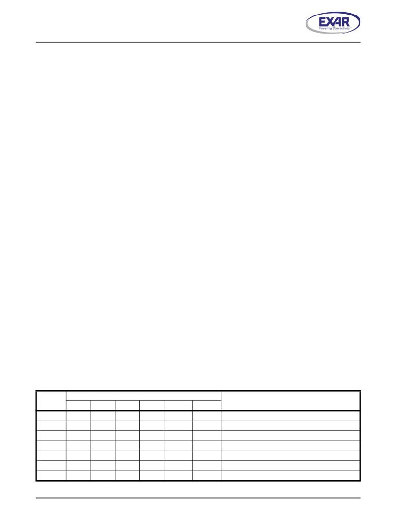
�T� ABLE� 9:� I� NTERRUPT� S� OURCE� AND� P� RIORITY� L� EVEL�
�P� RIORITY�
�ISR� R� EGISTER� S� TATUS� B� ITS�
�S� OURCE� OF� INTERRUPT�
�L� EVEL�
�B� IT� -5�
�B� IT� -4�
�B� IT� -3�
�B� IT� -2�
�B� IT� -1�
�B� IT� -0�
�1�
�2�
�3�
�4�
�5�
�7�
�-�
�0�
�0�
�0�
�0�
�0�
�1�
�0�
�0�
�0�
�0�
�0�
�0�
�0�
�0�
�0�
�1�
�0�
�0�
�0�
�0�
�0�
�1�
�1�
�1�
�0�
�0�
�0�
�0�
�1�
�0�
�0�
�1�
�0�
�0�
�0�
�0�
�0�
�0�
�0�
�0�
�0�
�1�
�LSR� (Receiver� Line� Status� Register)�
�RXRDY� (Receive� Data� Time-out)�
�RXRDY� (Received� Data� Ready)�
�TXRDY� (Transmit� Ready)�
�MSR� (Modem� Status� Register)�
�CTS#,� RTS#� change� of� state�
�None� (default)� or� Wake-up� Indicator�
�22�
�发布紧急采购,3分钟左右您将得到回复。
相关PDF资料
XRP2526EVB
BOARD EVAL POWER SWITCH XRP2526
XRP2528EVB
BOARD EVAL POWER SWITCH XRP2528
XT800SM
GAS TRIGGER TUBE 800V SMD
YMCRPR8C25
REF PLATFORM MOTOR CTRL R8C/25
ZB3251
INLINE FUSE HOLDER PLASTIC BODY
ZB3260
INLINE FUSE HOLDER BAKELITE BODY
ZB3270
PANEL MOUNT FUSE HOLDER
ZEN056V130A24GS
POLYZEN 5.6V PPTC/ZENER SMD
相关代理商/技术参数
XR18W750IL48
制造商:EXAR 制造商全称:EXAR 功能描述:WIRELESS UART CONTROLLER
XR18W750IL48-F
功能描述:UART 接口集成电路 UART RoHS:否 制造商:Texas Instruments 通道数量:2 数据速率:3 Mbps 电源电压-最大:3.6 V 电源电压-最小:2.7 V 电源电流:20 mA 最大工作温度:+ 85 C 最小工作温度:- 40 C 封装 / 箱体:LQFP-48 封装:Reel
XR18W750IL48TR-F
功能描述:UART 接口集成电路 XR18W750IL48TR-F RoHS:否 制造商:Texas Instruments 通道数量:2 数据速率:3 Mbps 电源电压-最大:3.6 V 电源电压-最小:2.7 V 电源电流:20 mA 最大工作温度:+ 85 C 最小工作温度:- 40 C 封装 / 箱体:LQFP-48 封装:Reel
XR18W753
制造商:EXAR 制造商全称:EXAR 功能描述:SINGLE CHIP 868MHZ TO 956MHZ RF TRANSCEIVER
XR18W753IL48
制造商:EXAR 制造商全称:EXAR 功能描述:SINGLE CHIP 868MHZ TO 956MHZ RF TRANSCEIVER
XR18W753IL48-F
功能描述:射频接收器 UART RoHS:否 制造商:Skyworks Solutions, Inc. 类型:GPS Receiver 封装 / 箱体:QFN-24 工作频率:4.092 MHz 工作电源电压:3.3 V 封装:Reel
XR18W753L48-0A-EB
功能描述:界面开发工具 900MHz RF EVAL Board
RoHS:否 制造商:Bourns 产品:Evaluation Boards 类型:RS-485 工具用于评估:ADM3485E 接口类型:RS-485 工作电源电压:3.3 V
XR1901SN
制造商:Electro-Term/Hollingsworth 功能描述: 制造商:Electro-Term/Hollingsworth 功能描述:16-14awg No. 6 stud ring terminal - FAC STK